![]()
![]()
Welcome to our tour/tutorial on the SpectraScanä Accent marking software. PC screen captures will be used to illustrate its tremendous power. SpectraScan Accent is 32-bit software combined with a dedicated board, the QMod32 laser computer on a board. The board outputs the scanner positions at 16-bit with up to 7 other signals available at a minimum of 8-bits. These signals can be used for continuous laser power control and other synchronous control requirements. There is also TTL blanking/gating and 16 bits of bidirectional IO for parts handling and other control functions. It would normally be used with Win95 but NT will also be a supported operating system. The software is available in modules as well for specific functions.
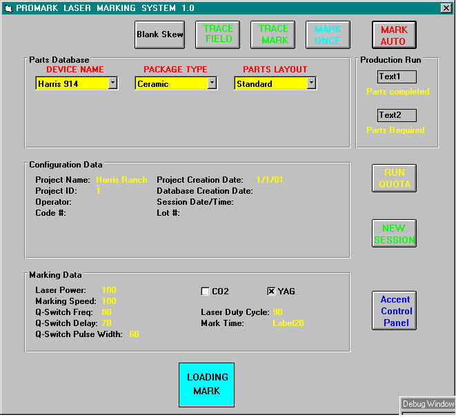
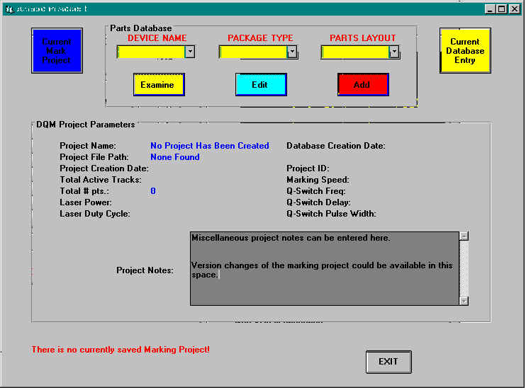
This first screen is the operator’s interface. It is password protected from the rest of the editing and mark or project creation environment. The operator on the machine might never go beyond this interface. You can see the parts choices which are related to an Access database. Once you choose this discrete entry, the marking project connected to it is loaded and ready to mark under single or batch quantities. It will automatically apply your rules for conditions in the handling equipment or sensors before marking and outputs signals at the end of each cycle to trigger necessary equipment. You can see the operator can check information on the marking project such as laser power level and parts quota. The entry can show shift data and operator’s name. This screen will indicate parts completed and time required and estimated to completion of the batch run.
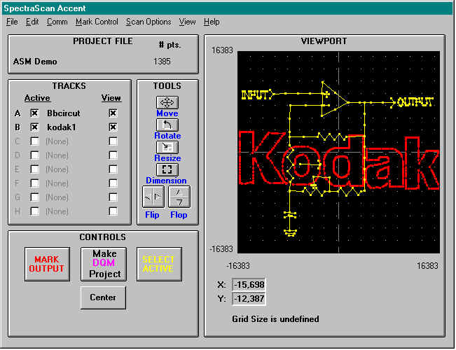
If you press the "Accent Control Panel", you go to the main interface and editing window. From here are multiple menu choices for the many options you can chose from. From File, you can load projects or individual frame images. The interface is designed to accept up to 8 separate marking screens of data. Their names and your option as to whether they are viewable or included in the current project are indicated by checkmarks. These images can all be sequentially marked. For example, maybe one is the company logo, another the date, and 3 of them name and number designations that vary by bin selection in real time. The viewport which shows the marks has position data that can be in logical coordinates or cm or inches based on the scan head mechanical spacing. You can zoom back and forth for the full view or fine details. Grids and origin lines are menu selectable options. You see the tool buttons next to the viewport. On screen with these tools, you can move, resize, or rotate the images selectively by track or by cursor-box selected subsets of the image. There is also a dimension tool which is an on-screen ruler. Finally, you can flip the images around a chosen axis. All the editing tools can be entered numerically for perfect accuracy in the Transform Window. After setting all parameters in the different menus, you create a project here and can assign it to some database part.
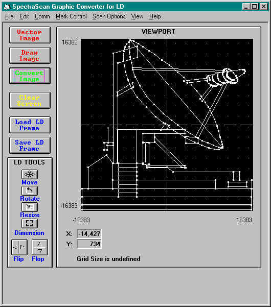
The following all some of the screens from menu selection. You can auto convert vector
drawn images such as Corel or AutoCad files in the following module. It can also load a
small drawing program allowing you to create images within Accent. Here is a satellite
image that was converted for marking use.
This is a screen for manual editing of images. It will change to the unit of measurement that has been selected.
![]()
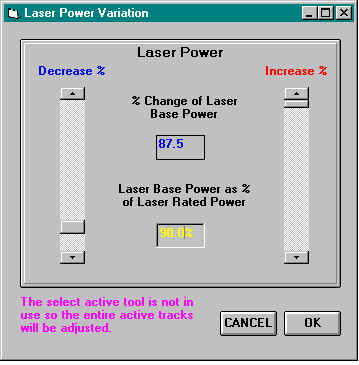
Here you can select laser power. This can be done using the active screen selector so that you can change power for any point in the mark. No other software can do this.
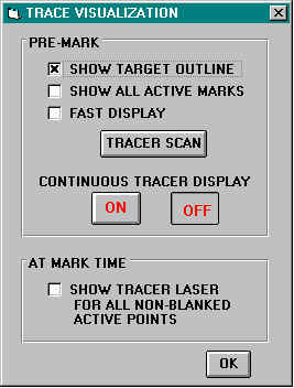
Here are some more option screens for trace viewing of laser diode and setting of the physical parameters of the scan head and the distance to the work piece. This one shown is based on General Scanning’s 3-axis variable focus system.
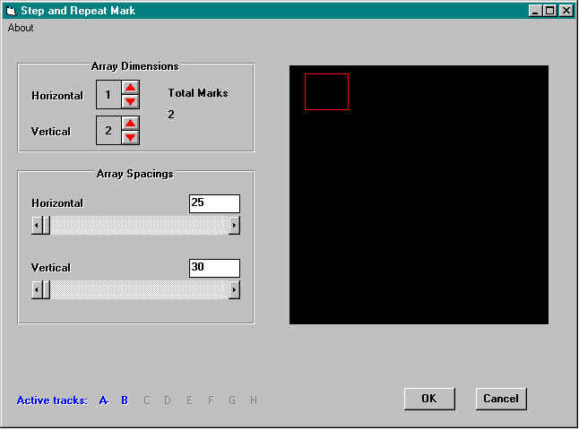
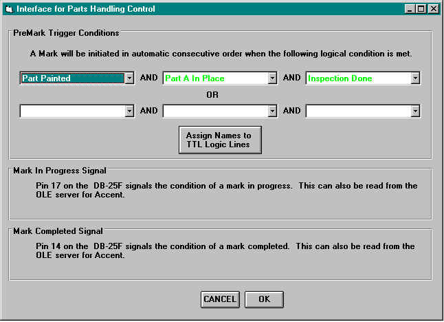
Here are screens for Step and Repeat settings and for Parts Handling Interface. Notice the ease of setup. Also, the innovative use of assignment names to actual output ports before you create the boolean statements necessary to initiate marking.
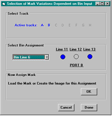
You can preset changes in mark data based on inputs to a set of three IO ports for on-the-fly bin variations.
Finally, a completed project with all its images, power settings, blank delays, laser settings, etc. can be assigned to a described part in the database. Notice that different display colors correlate to a current project saved and others to previous settings for the database object. This allows easy editing between old and new information. For example, if you wanted almost all the settings for some previous part and a few new settings in a current project, you could load from the previous part in the database. Then you enter the current settings and be selective about which data will be retained before saving as a new part (or upgrade of a old part). The information is viewable by toggling back and forth between the two data-views.
I hope this introduction makes an understanding of our software a little easier. Please address your further questions to lasermarking@lasershs.com.
![]()
![]()
![]()
![]()
![]()
![]()
![]()